Su perposition Ex a mple s
The following examples illustrate the proper use of superposition of dependent sources. All superposition
equations are written by inspection using voltage division, current division, series-parallel combinations, and
Ohm’s law. In each case, it is simpler not to use superposition if the dependent sources remain active.
Example 1
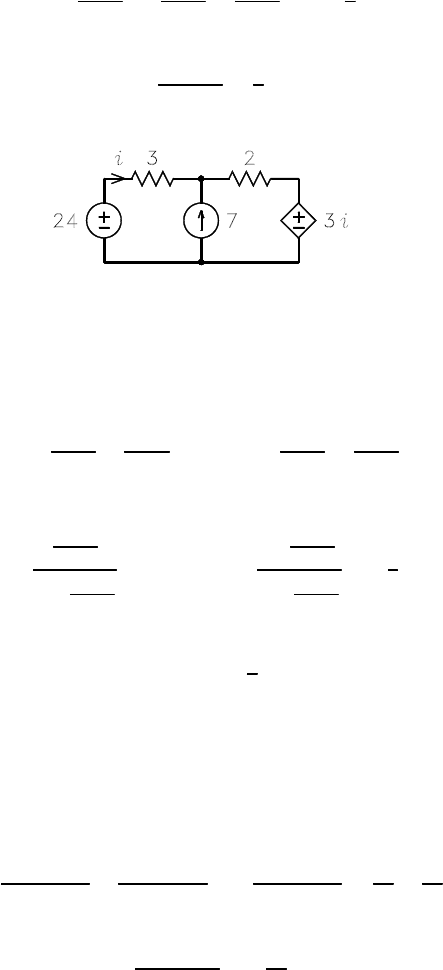
Theobjectistosolveforthecurrenti in the circuit of Fig. 1. By superposition, one can write
i =
24
3+2
− 7
2
3+2
−
3i
3+2
=2−
3
5
i
Solution for i yields
i =
2
1+3/5
=
5
4
A
Figure 1: Circuit for example 1.
If superposition of the controlled source is not used, two solutions must be found. Let i = i
a
+i
b
,wherei
a
is the current with the 7Asource zeroed and i
b
is the current with the 24 V source zeroed. By superposition,
we can write
i
a
=
24
3+2
−
3i
a
3+2
i
b
= −7
2
3+2
−
3i
b
3+2
Solution for i
a
and i
b
yields
i
a
=
24
3+2
1+
3
3+2
=3A i
b
=
−7
2
3+2
1+
3
3+2
= −
7
4
A
The solution for i is thus
i = i
a
+ i
b
=
5
4
A
This is the same answer obtained by using superposition of the controlled source.
Example 2
The object is to solve for the voltages v
1
and v
2
across the current sources in Fig. 2, where the datum node
is the lower branch. By superposition, the current i is given b y
i =2
7
7+15+5
+
3
7+15+5
+4i
7+15
7+15+5
=
17
27
+
88
27
i
Solution for i yields
i =
17/27
1 − 88/27
= −
17
61
A
Although superposition can be used to solve for v
1
and v
2
, it is simpler to write
v
2
=5i = −1.393 V v
1
= v
2
− (4i − i)15= 11.148 V
1
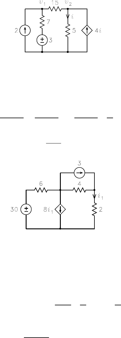
Figure 2: Circuit for example 2.
Example 3
Theobjectistosolveforthecurrenti
1
in the circuit of Fig. 3. By superposition, one can write
i
1
=
30
6+4+2
+3
4
6+4+2
− 8i
1
6
6+4+2
=
42
12
− 4i
1
Solution for i
1
yields
i
1
=
42/12
1+4
=0.7A
Figure 3: Circuit for example 3.
Example 4
The object is to solve for the Thévenin equivalent circuit seen looking into the terminals A− A
0
in the circuit
of Fig. 4. By superposition, the voltage v
x
is given by
v
x
=(3− i
o
)(2k40) + 5v
x
2
40 + 2
=
80
42
(3 − i
o
)+
10
42
v
x
where i
o
is the current drawn by any external load and the symbol “k” denotes a parallel combination.
Solution for v
x
yields
v
x
=
80/42
1 − 10/42
(3 − i
o
)=2.5(3− i
o
)
Although superposition can be used to solve for v
o
,itissimplertowrite
v
o
= v
x
− 5v
x
= −30 + 10i
o
It follows that the Thévenin equivalent circuit consists of a −30 V source in series with a −10 Ω resistor. The
circuit is shown in Fig. 5.
2
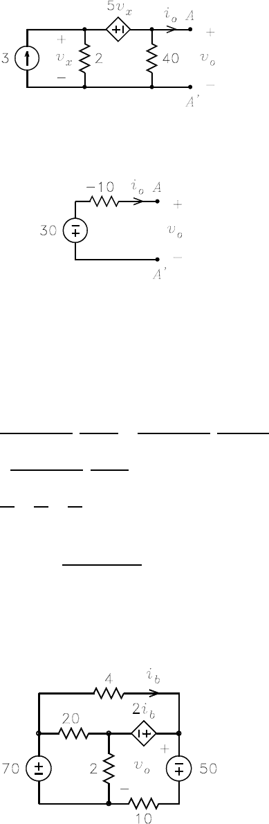
Figure 4: Circuit for example 4.
Figure 5: Thévenin equivalent circuit.
Example 5
The object is to solve for the voltage v
o
in the circuit of Fig. 6. By superposition, the current i
b
is given by
i
b
=
70
4k20 + 2k10
20
4+20
+
50
10 + 4k20k2
20k2
4+20k2
−
2i
b
20k2+4k10
10
4+10
=
35
3
+
25
18
−
11
36
i
b
Solution for i
b
yields
i
b
=
35/3+25/18
1+11/36
=10A
Although superposition can be used to solve for v
o
, it is simpler to write
v
o
=70− 4i
b
=30V
Figure 6: Circuit for example 5.
3
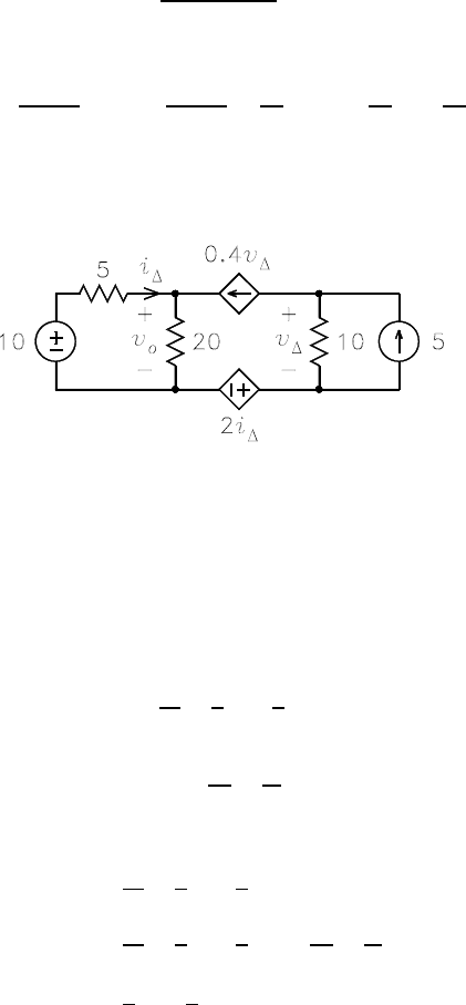
Example 6
The object is to solve for the voltage v
o
in the circuit of Fig. 7. By superposition, the voltage v
∆
is given by
v
∆
= −0.4v
∆
× 10 + 5 × 10
Thiscanbesolvedforv
∆
to obtain
v
∆
=
5 × 10
1+0.4 × 10
=10V
By superposition, i
∆
is given by
i
∆
=
10
5+20
− 0.4v
∆
20
20 + 5
=
10
25
− 0.4v
∆
20
25
= −
70
25
A
Thus v
o
is given by
v
o
=10− 5i
∆
=24V
Figure 7: Circuit for example 6.
Example 7
The object is to solve for the voltage v as a function of v
s
and i
s
in the circuit in Fig. 8. By superposition,
the current i is given by
i =
v
s
5
−
2
5
i
s
−
3
5
× 3i
Thiscanbesolvedfori to obtain
i =
v
s
14
−
i
s
7
By superposition, the voltage v is given by
v =
v
s
5
−
2
5
i
s
+
2
5
× 3i
=
v
s
5
−
2
5
i
s
+
2
5
× 3
µ
v
s
14
−
i
s
7
=
2
7
v
s
−
4
7
i
s
Example 8
This example illustrates the use of superposition in solving for the dc bias currents in a BJT. The object is to
solve for the collector current I
C
in the circuit of Fig. 9. Although no explicit dependent sources are shown,
the three BJT currents are related b y I
C
= βI
B
= αI
E
,whereβ is the current gain and a = β/ (1 + β).If
an y one of the currents is zero, the other t wo must also be zero. However, the currents can be treated as
independent variables in using superposition.
4
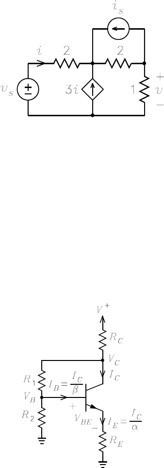
Figure 8: Circuit for Example 7.
Figure 9: Circuit for example 8.
5

By superposition of V
+
, I
B
= I
C
/β,andI
C
, the voltage V
B
is given by
V
B
= V
+
R
2
R
C
+ R
1
+ R
2
−
I
C
β
[(R
C
+ R
1
) kR
2
]
−I
C
R
C
R
2
R
C
+ R
1
+ R
2
A node-voltage solution for V
B
requires the solution of two sim u ltaneous equations to obtain the same answer
which superposition yields by inspection. This equation and the equation
V
B
= V
BE
+
I
C
α
R
E
canbesolvedforI
C
to obtain
I
C
=
V
+
R
2
R
C
+R
1
+R
2
− V
BE
(R
C
+R
1
)kR
2
β
+
R
C
R
2
R
C
+R
1
+R
2
+
R
E
α
In most contemporary electronics texts, the value V
BE
=0.7V is assumed in BJT bias calculations.
Example 9
This example illustrates the use of superposition to solve for the small-signal base input resistance of a BJT.
Fig. 10 shows the small-signal BJT hybrid-pi model with a resistor R
E
fromemittertogroundandaresistor
R
C
from collector to ground. In the model, r
π
= V
T
/I
B
and r
0
=(V
A
+ V
CE
) /I
C
,whereV
T
is the thermal
voltage, I
B
isthedcbasecurrent,V
A
is the Early voltage, V
CE
is the dc collector-emitter voltage, and I
C
isthedccollectorcurrent.
Figure 10: Circuit for example 9.
By superposition of i
b
and βi
b
, the base voltage v
b
is given by
v
b
= i
b
[r
π
+ R
E
k (r
0
+ R
C
)] + βi
b
r
0
R
E
+ r
0
+ R
C
R
E
This can be solved for the base input resistance r
ib
= v
b
/i
b
to obtain
r
ib
= r
π
+ R
E
k (r
0
+ R
C
)+
βr
0
R
E
R
E
+ r
0
+ R
C
which simplifies to
r
ib
= r
π
+ R
E
(1 + β) r
0
+ R
C
R
E
+ r
0
+ R
C
A node-voltage solution for r
ib
requires the solution of three simultaneous equations to obtain the same
answer which follows almost trivially by superposition.
6
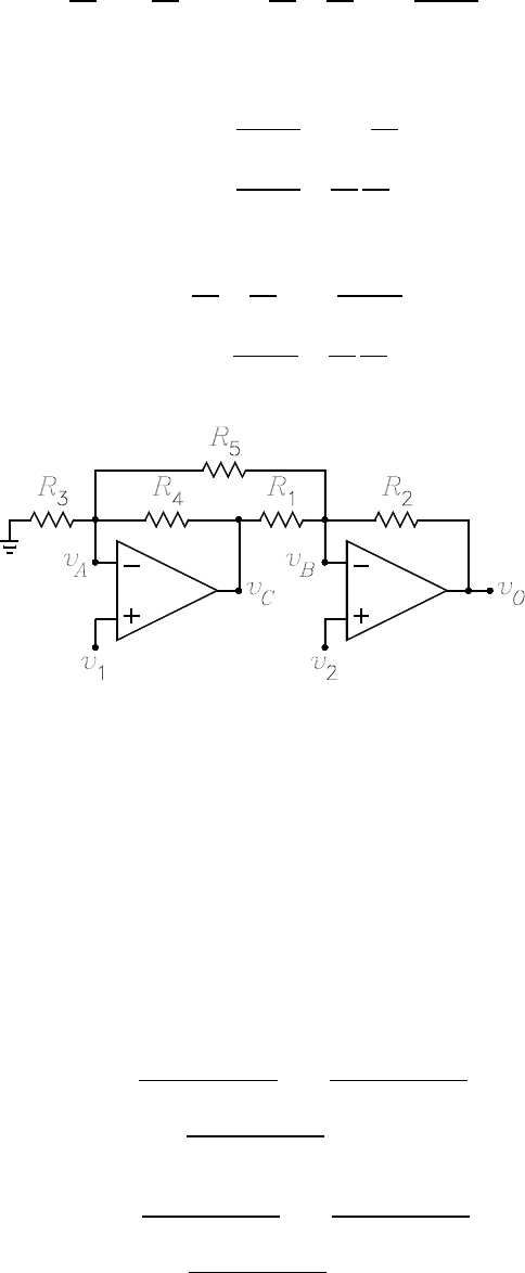
Example 10
This example illustrates the use of superposition with an op-amp circuit. The circuit is sho wn in Fig. 11.
The object is to solve for v
O
.Withv
2
=0, it follows that v
A
= v
1
, v
B
=0,andv
C
=[1+R
4
/ (R
3
kR
5
)] v
1
.
By superposition of v
A
and v
C
, v
O
can be written
v
O
= −
R
2
R
5
v
A
−
R
2
R
1
v
C
= −
·
R
2
R
5
+
R
2
R
1
µ
1+
R
4
R
3
kR
5
¶¸
v
1
With v
1
=0, it follows that v
A
=0, v
B
= v
2
,andv
C
= − (R
4
/R
5
) v
2
. By superposition of v
2
and v
C
, v
O
can be written
v
O
=
µ
1+
R
2
R
1
kR
5
v
2
−
R
2
R
1
v
C
=
µ
1+
R
2
R
1
kR
5
+
R
2
R
1
R
4
R
5
v
2
Th us the total expression for v
O
is
v
O
= −
·
R
2
R
5
+
R
2
R
1
µ
1+
R
4
R
3
kR
5
¶¸
v
1
+
µ
1+
R
2
R
1
kR
5
+
R
2
R
1
R
4
R
5
v
2
Figure 11: Circuit for Example 10.
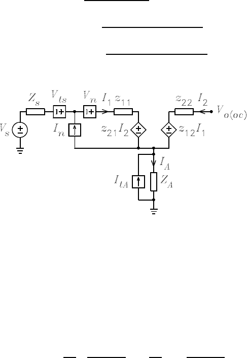
Example 11
Figure 12 shows a circuit that might be encountered in the noise analysis of amplifiers. The amplifier is
modeled b y a z-parameter model. The square sources represent noise sources. V
ts
and I
tA
, respectively,
model the thermal noise generated by Z
x
and Z
A
. V
n
and I
n
model the noise generated by the amplifier.
The amplifier load is an open circuit so that I
2
=0. The open-circuit output voltage is given by
V
o(oc)
= z
12
I
1
+ I
A
Z
A
By superposition, the currents I
1
and I
A
are given by
I
1
=
V
s
+ V
ts
+ V
n
Z
S
+ Z
A
+ z
11
+ I
n
Z
S
+ Z
A
Z
S
+ Z
A
+ z
11
−I
tA
Z
A
Z
S
+ Z
A
+ z
11
I
A
=
V
s
+ V
ts
+ V
n
Z
S
+ Z
A
+ z
11
− I
n
z
11
Z
S
+ Z
A
+ z
11
+I
tA
Z
S
+ z
11
Z
S
+ Z
A
+ z
11
7
Note that when I
n
=0,thesourcesV
s
, V
ts
,andV
n
are in series and can be considered to be one source
equal to the sum of the three. When these are substituted into the equation for V
o(oc)
and the equation is
simplified, we obtain
V
o(oc)
=
z
21
+ Z
A
Z
S
+ Z
A
+ z
11
h
V
s
+ V
ts
+ V
n
+I
n
(Z
S
+ Z
A
) z
21
− Z
A
z
11
z
21
+ Z
A
−I
tA
Z
A
z
21
− (Z
S
+ z
11
) Z
A
z
21
+ Z
A
i
Figure 12: Circuit for Example 11.
Example 12
It is commonly believed that superposition can only be used with circuits that have more than one source.
This example illustrates how it can be use with a circuit having one. Consider the first-order all-pass filter
shown in Fig. 13(a). An equivalent circuit is shown in Fig. 13(b) in which superposition can be used to
write by inspection
V
o
=
µ
1+
R
1
R
1
RCs
1+RCs
V
i
−
R
1
R
1
V
i
=
RCs − 1
RCs +1
V
i
8

Figure 13: Circuit for Example 12.
9
